
In this post I’ll describe positioning results obtained by applying RTK on data from timing enabled GPS chips. I don’t have centimeter level accuracy yet, but I hope that some of the work I have done can benefit others who are experimenting with RTK. As described in my earlier post, you need special GPS chips that provide raw timing data in order to use RTK.
Hardware/Software Required to Follow this Post:
- Two timing enabled GPS chips (for example the uBlox 6t or the 8mt) that can be connected to a computer through USB
- RTK lib install (http://www.rtklib.com/)
- A CORS (Continously Operating Reference Station) base station (optional)
I found it odd that I couldn’t find any vendors that shipped consumer grade (< 300$) timing enabled GPS chips within the US. uBlox is the only vendor I’m aware that makes consumer grade GPS chips. At the time of this writing, if you search on Amazon or eBay for the timing enabled uBlox chips (the 6t or the 8mt), the only vendor that appears is Hobbypower that ships from China. Another vendor is csgshop (http://www.csgshop.com/), but they ship from Latvia in Europe and I’ve had bad experiences ordering hardware from them. There are no timing enabled GPS chips available from Hobbyking, a popular supplier of DIY electronics in the US. For my experiments, I used the Lea-6T GPS chips shipped by Hobbypower. The circuit board has an on-board FTDI chip that makes it easy to connect to a USB port on a PC.
After spending two weeks in transit, my Lea-6T chips finally showed up. Here’s how they look:
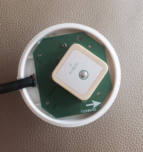
As you can see, the 2.5*2.5*0.4 cm patch antenna is rigidly attached to the circuit board, hence there is no way to attach a better antennae to this setup. This is a major limitation, as a good antenna is critical to obtaining good RTK results.
The goal of my investigation was to obtain the accurate GPS position of my rover given a fixed base station. My setup consisted of:
- Rover: one of the GPS units connected to my PC
- Base Station: I tried two options for the base station
- The nearest CORS (Continuously Operating Reference Station)
- The second GPS chip.
We’ll examine both of these options in detail below.
First, the rover setup. I connected one of the GPS units to my Windows 7 PC through a USB cable. Upon running u-center (GNSS software that can be downloaded from ublox website), I was able to connect to the serial port and see the satellite positions and GPS fix. The default baud rate for the ublox chips is 9600, so that’s a good place to start.
The rest of the procedure differs between the two choices of the base station. Let’s first consider using the CORS station as the base station.
CORS Base Station:
The main idea behind a base station is to provide the differential GPS system an alternate source of GPS observations whose position is known and that can therefore be used to estimate the errors arising from upper atmospheric disturbances and signal phase estimation. I used the CORS data supplied by National Geodetic Survey (NGS). There are CORS stations located all over the country. A list can be found here (http://www.ngs.noaa.gov/cgi-cors/CorsSidebarSelect.prl?site=loyb&option=Standard%20Files). Select the location closest to you (http://www.ngs.noaa.gov/UFCORS/), the time for which you want the GPS data and download the CORS data file and the IGS orbits. CORS doesn’t provide real time data. The latest data available is for the previous hour. Therefore, CORS data must be combined with the rover data in a post process step (as opposed to applying real time corrections).
The CORS data consists of the GPS observation data (.o extension), Navigation data (.n extension), satellite orbit information (.sp3 extension) and a text file containing the station coordinates. These files are RINEX text files and can be viewed in a text editor such as notepad++. I’ll describe the contents of these files in a future post.
Step 1: Obtain RAW GPS Data
In order to obtain real time rover information, you connect the ublox GPS receiver to a serial port on your computer and open strsvr, one of binaries in your RTK lib distribution.
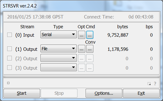
Under the command options, enter the following:
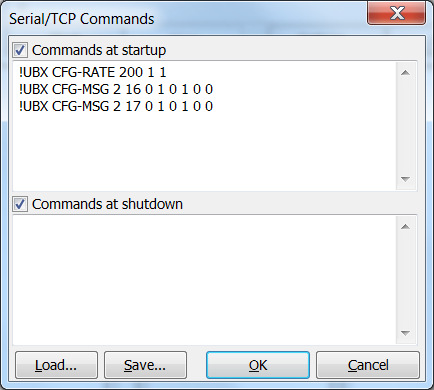
The CFG-RATE command sets the Measurement Period to 200ms giving us 5 Hz position update. The CFG-MSG commands turn on the RXM-RAW and RXM-SFRB messages that provide the raw information needed for RTK calculations. For more information, see https://wiki.openstreetmap.org/wiki/UbloxRAW#UBX_messages_providing_raw_measurements.
For the conversion option, select conversion to RTCM3 format and specify the following RTCM messages.
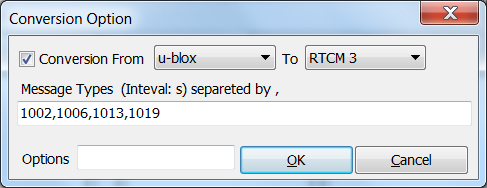
RTCM (Radio Technical Commission for Maritime Services) is a compact binary data format for transmitting GPS correction information. RTCM data consists of several message types describing various type of data. Each message consists of a header and a body with the header describing the message type, time and length, and the body containing the message data. Being a binary format, if you open RTCM data in a text browser, it will appear as gibberish. It will need to be parsed to extract the content of various message types.
The RTCM messages we need are:
- 1002: GPS L1 observations, extended information
- 1006: ARP station coordinates in different formats (ECEF, XYZ) along with antennae height.
- 1013: System parameters, update rates
- 1019: GPS Ephemeris
Note that we don’t use the 1003/1004 messages as the Lea 6T doesn’t provide L2 band GPS observations.
You can keep the rover still or move it around (preferably in a known pattern, so you can compare the positioning results with the actual position of the rover). Collect data for at least 15 minutes.
Step 2: Convert RTCM to RINEX
Once we have collected enough data, we convert the rover RTCM data into RINEX. We need to do so as the utility we’ll be using to run the RTK calculations, rtkpost needs the base station and rover data in RINEX format. We’ll use rtkconv to convert our RTCM data to Rinex.
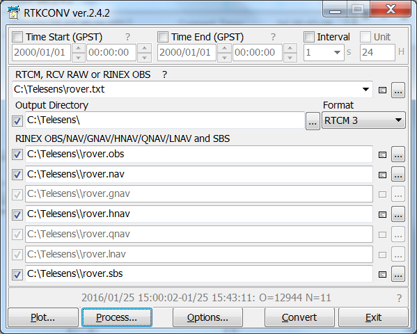
Few things to note:
- You don’t need to specify the Time Start/Time End (unless you want to select a subset of the time interval over which you collected the rover data). rtkconv will automatically calculate the observation time interval and display this information along with the number of observation samples.
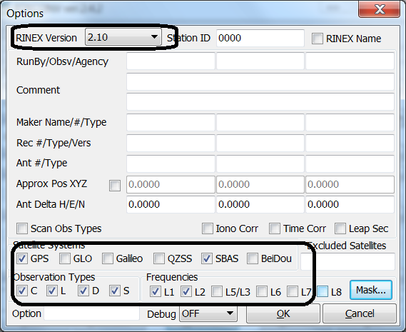
- In the rtkconv options, ensure that Rinex 2.10 is selected and GPS, SBAS, and L1 checkboxes are checked.
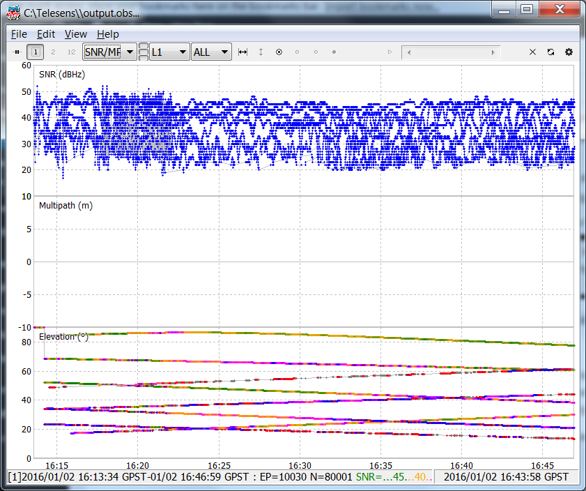
you can also use the rtkconv plot utility to view the satellite track and the signal/noise ratio of the satellite signal. The signal/noise ratio should be around 50. Lower numbers are better. Using a better antenna will lead to better SNR. Also, conducting your experiment in an open area with an open view of the sky helps with improving the SNR.
Step 3: Using RTKPost to apply RTK Corrections
Now that we have the rover and base station observations in the correct format, the last step is to use rtkpost utility to apply the base station corrections. An important step in this process is to specify the base station coordinates in the rtkpost options. If you fail to do so, rtkpost will not apply any corrections and you will not get any accuracy improvements.
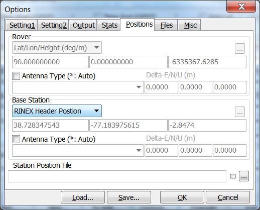
To specify the base station coordinates, you can either enter them manually, or say “RINEX Header Position” and they’ll be pulled in from the base station RINEX file.
Hit execute to run rtkpost. If all goes well, you’ll be able to see the corrected positions by hitting plot and selecting Gnd Trk.
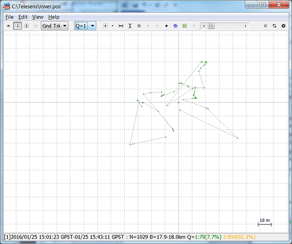
You’ll notice that there are 6 types of fixes indicating the solution quality (page 102 of the rtklib manual)
- Q=1: Fixed, solution by carrier-based relative positioning and the integer ambiguity is properly resolved
- Q=2: Float, solution by carrier-based relative positioning but the integer ambiguity is not resolved
- Q=3: Reserved
- Q=4: DGPS, solution by code-based DGPS solutions or single point positioning with SBAS corrections
- Q=5: Single No corrections are applied, solution by single point positioning. If you omit the base station position, you’ll get a fix of this type.
We want to have Q=1 or 2 type fixes. In my experiment, I got mostly type 2 fixes, however as you can see, the accuracy wasn’t very good (even for type 1 fix).
Using a Lea-6T as a Base Station
As you have likely noticed, there are two major issues with using the CORS as base station. First the accuracy is bad. We’ll look at some of the reasons for this in the next section. Second, since the CORS station I’m using doesn’t provide real time observations, this method can only be used where real time positioning is not required. In order to use RTK in real time, we need the base station observations concurrently with the rover observations. This can be set up by using a second timing enabled GPS device and feeding its output to rtknavi.
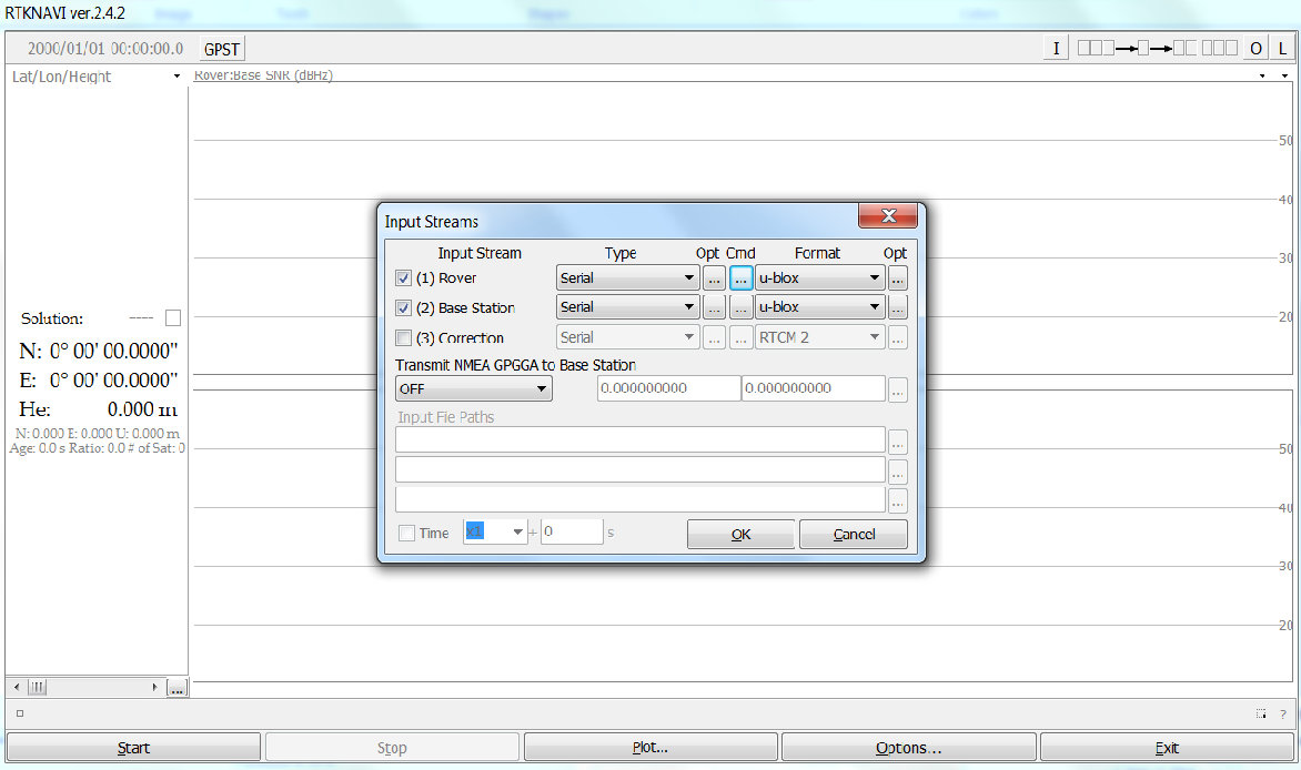
The input streams are easy to set up. Make sure to provide the configuration commands in the “commands at startup” while setting up the input streams from the rover and base station. The relative location of the base station and the rover doesn’t seem to be important. I simply kept the base station at a fixed location on the ground and held the rover in my hand so I could move it around. Just as we did with rtkpost, we’ll need to specify the position of the base station. I simply noted the position of the base station by zooming in my position in google maps.
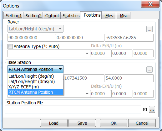
The position I obtained from Google maps is clearly not of cm level accuracy and I’m not sure by how much the performance of rtknavi depends on the exact specification of the base station. Certainly the error in the absolute position of the rover will depend on the error in the specification of the base station, but I’m not sure how sensitive is the relative position of the rover to the absolute position of the base station.
Upon running rtknavi, I was able to obtain a floating fix within about 45 seconds and occasionally a full fix. The output looks like this:
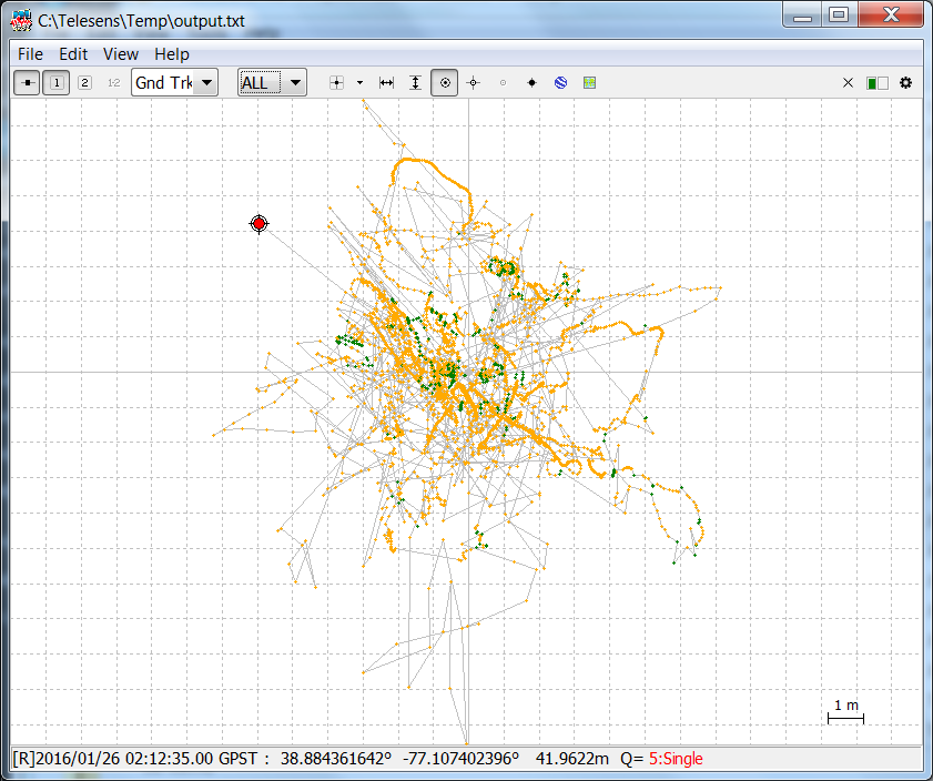
The few times I was able to get a fix, the rover position on the map would correspond exactly to the rover held in my hand as I was moving it my around, which was very cool to see. However most of the time, the rover position on the map was moving around in a random walk even though I was holding the rover still.
Factors Affecting Accuracy
I believe the major reason I’m not able to obtain cm level accuracy that I was expecting is that I’m using the stock patch antennae that came with the lea-6t. I’m investing in some better antennae and ordered new hardware that allows me to use external antennae. As mentioned before, the patch antennae that came with the lea-6t are rigidly attached to the circuit board, so connecting external antennae isn’t an option with the current hardware.
Another point to consider is that most consumer grade GPS hardware that I’ve come across only provides access to L1 band data. I was wondering if using L2 band data would lead to better accuracy. I posted the question on various GNSS forums and some people responded that if the distance between the base station and the rover is < 10km, dual band receivers don’t lead to better accuracy. In the post processing example where I was using CORS data, the CORS base station is located >18 km from my rover. Apparently that is a bit too far, so using a closer CORS station will lead to better accuracy. Additionally the location where I conducted my experiment was surrounded by buildings on one side. Next time I will pick an open field and report back the results.
Thanks a lot for the post. I had been stuck on how to get a Q=1 or 2 solution but wasn’t able to. Your step by step method helped me achieve it.
Glad you found it helpful!