

In this post, I’ll describe the lessons learnt from trying to sample IMU sensors to obtain raw gyroscope and accelerometer data as input to sensor fusion algorithms using the Raspberry Pi.
Pose (orientation) computation by combining angular velocity data collected from gyroscopes and acceleration data from accelerometers is an important first step in a variety of AR/VR applications. The sensor fusion is typically done using complimentary filters or kalman filters. High speed, constant rate sampling of the sensor data is important for optimal performance of the sensor fusion algorithms.
In our experiments, we took an MPU6050 and MPU9250 sensor from Invensense and connected them to a Raspberry Pi 3 as shown in the figure below. The MPU 9250 was selected as it hosts a magnetometer in addition to the accelerometer and gyroscope.
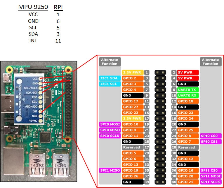
The second IMU (MPU 6050) is also connected to the SCL and SDA lines. It is possible to connect multiple I2C devices on the same lines as long as they have different addresses. The default address of the MPU 6050/9250 is 0x68. This can be changed to 0x69 by connecting ADO pin to VCC. The interrupt pin of the second IMU is connected to GPIO 27 (Pin 13).
To verify that the IMUs are registered properly, run i2cdetect -y 1 on the Pi console. You should see the two devices at 0x68 and 0x69.
Software Architecture
To set my interrupt service routines and receive sensor data over the I2C bus, I use the WiringPi library by Gord)on (http://wiringpi.com/). The library provides convenient read/write functions that allow for read/writes from/to specific registers on I2C devices connected to the Pi and registering interrupt service routines to receive callbacks when interrupts arrive at a GPIO pin.
For reading data from the MPU9250, I took the corresponding code for the MPU6050 developed by Jeff Rowberg and re implemented the functions that I needed such as setting the gyro/accel low pass filter settings and sampling rates, obtaining the raw sensor values by reading the appropriate registers and setting various interrupt flags. Note that while most of architecture (registers, bit locations, bit lengths etc) is the same for the MPU6050/9250, there are some differences. For example, the MPU9250 allows for setting a low pass filter on the accelerometer and the gyroscope independently. The bandwidth and delay values for the various low pass filter settings are also slightly different between the two MPU’s.
The implementation of some of the functions is shown below. The variable fd shown in the code below refers to the descriptor returned after calling wiringPiI2CSetup(addr). The variable addr is the address of the I2C device (0x68 or 0x69).
|
1 2 3 4 5 6 7 8 9 10 11 12 13 14 15 16 17 18 19 20 21 22 23 24 25 26 27 28 29 30 31 32 33 34 35 36 37 38 39 40 41 42 43 44 45 46 47 48 49 50 51 52 53 54 55 56 57 |
/** Set digital low-pass filter configuration. * @param mode New DLFP configuration setting * @see getDLPFBandwidth() * @see MPU9250_DLPF_BW_256 * @see MPU9250_CONFIG * @see MPU9250_CFG_DLPF_CFG_BIT * @see MPU9250_CFG_DLPF_CFG_LENGTH * <pre> * mode: FCHOICE A_DLPF BW(Hz) Delay(ms) Noise Density Rate (KHz) 0 X 1.13K 0.75 250 4 1 0 460 1.94 250 1 1 1 184 5.80 250 1 1 2 92 7.80 250 1 1 3 41 11.80 250 1 1 4 20 19.80 250 1 1 5 10 35.70 250 1 1 6 5 66.96 250 1 1 7 460 1.94 250 1 * </pre> */ void MPU9250::setAccelDLPFMode(uint8_t mode) { // First set the fchoice_b bits, see pg 14 of the register doc I2C_Pi::writeBits(fd, MPU9250_ACCEL_CONFIG2, MPU9250_ACCEL_FCHOICEB_BIT, MPU9250_ACCEL_FCHOICEB_BIT_LENGTH, 0); I2C_Pi::writeBits(fd, MPU9250_ACCEL_CONFIG2, MPU9250_ACCEL_CFG_DLPF_CFG_BIT, MPU9250_ACCEL_CFG_DLPF_CFG_LENGTH, mode); } /** Get full-scale accelerometer range. * The FS_SEL parameter allows setting the full-scale range of the accelerometer * sensors, as described in the table below. * * <pre> * 0 = +/- 2g * 1 = +/- 4g * 2 = +/- 8g * 3 = +/- 16g * </pre> * * @return Current full-scale accelerometer range setting * @see MPU9250_ACCEL_FS_2 * @see MPU9250_ACCEL_CONFIG * @see MPU9250_ACONFIG_AFS_SEL_BIT * @see MPU9250_ACONFIG_AFS_SEL_LENGTH */ uint8_t MPU9250::getFullScaleAccelRange() { I2C_Pi::readBits(fd, MPU9250_ACCEL_CONFIG, MPU9250_ACONFIG_AFS_SEL_BIT, MPU9250_ACONFIG_AFS_SEL_LENGTH, buffer); return buffer[0]; } /** Set full-scale accelerometer range. * @param range New full-scale accelerometer range setting * @see getFullScaleAccelRange() */ void MPU9250::setFullScaleAccelRange(uint8_t range) { I2C_Pi::writeBits(fd, MPU9250_ACCEL_CONFIG, MPU9250_ACONFIG_AFS_SEL_BIT, MPU9250_ACONFIG_AFS_SEL_LENGTH, range); } |
Jeff Rowberg’s implementation of the MPU6050 driver is intended for the Arduino hardware and uses the Arduino I2CDev library for register read/write operations. The I2CDev library in turn uses the Arduino Wire library for the low level I2C operations. Since my implementation of the MPU9250 driver is intended to run on the Raspberry Pi, I reimplemented portions of the I2CDev library for the Pi and rerouted the low level register access functions through the WiringPi library. Some relevant code samples are shown below.
|
1 2 3 4 5 6 7 8 9 10 11 12 13 14 15 16 17 18 19 20 21 22 23 24 25 26 27 28 29 30 31 32 33 34 35 36 37 38 39 40 41 42 43 44 45 46 47 48 49 50 51 52 53 54 55 56 57 58 59 60 61 62 63 64 65 66 67 68 69 70 71 72 73 74 75 76 77 78 79 80 81 82 83 84 85 86 87 88 89 90 91 92 93 94 95 96 97 98 99 100 101 102 103 104 105 |
8_t I2C_Pi::readBits(uint8_t devAddr, uint8_t regAddr, uint8_t bitStart, uint8_t length, uint8_t *data) { // 01101001 read byte // 76543210 bit numbers // xxx args: bitStart=4, length=3 // 010 masked // -> 010 shifted int8_t count; uint8_t b; if ((count = readByte(devAddr, regAddr, &b)) != -1) { uint8_t mask = ((1 << length) - 1) << (bitStart - length + 1); b &= mask; b >>= (bitStart - length + 1); *data = b; } return count; } /** Read single byte from an 8-bit device register. * @param devAddr I2C slave device address * @param regAddr Register regAddr to read from * @param data Container for byte value read from device * @return Status of read operation (-1 for failure, success otherwise) */ int8_t I2C_Pi::readByte(uint8_t devAddr, uint8_t regAddr, uint8_t *data ) { return readBytes(devAddr, regAddr, 1, data); } /** Read multiple bytes from an 8-bit device register. * @param devAddr I2C slave device address * @param regAddr First register regAddr to read from * @param length Number of bytes to read * @param data Buffer to store read data in * @return Number of bytes read (-1 indicates failure) */ int8_t I2C_Pi::readBytes(uint8_t devAddr, uint8_t regAddr, uint8_t length, uint8_t *data ) { for (int i = 0; i < length; i++) { int ret = wiringPiI2CReadReg8(devAddr, regAddr++); if (ret == -1) return -1; data[i] = ret; } return length; } /** Write multiple bits in an 8-bit device register. * @param devAddr I2C slave device address * @param regAddr Register regAddr to write to * @param bitStart First bit position to write (0-7) * @param length Number of bits to write (not more than 8) * @param data Right-aligned value to write * @return Status of operation (true = success) */ bool I2C_Pi::writeBits(uint8_t devAddr, uint8_t regAddr, uint8_t bitStart, uint8_t length, uint8_t data) { // 010 value to write // 76543210 bit numbers // xxx args: bitStart=4, length=3 // 00011100 mask byte // 10101111 original value (sample) // 10100011 original & ~mask // 10101011 masked | value uint8_t b; if (readByte(devAddr, regAddr, &b) != 0) { uint8_t mask = ((1 << length) - 1) << (bitStart - length + 1); data <<= (bitStart - length + 1); // shift data into correct position data &= mask; // zero all non-important bits in data b &= ~(mask); // zero all important bits in existing byte b |= data; // combine data with existing byte return writeByte(devAddr, regAddr, b); } else { return false; } } /** Write single byte to an 8-bit device register. * @param devAddr I2C slave device address * @param regAddr Register address to write to * @param data New byte value to write * @return Status of operation (true = success) */ bool I2C_Pi::writeByte(uint8_t devAddr, uint8_t regAddr, uint8_t data) { return writeBytes(devAddr, regAddr, 1, &data); } /** Write multiple bytes to an 8-bit device register. * @param devAddr I2C slave device address * @param regAddr First register address to write to * @param length Number of bytes to write * @param data Buffer to copy new data from * @return Status of operation (true = success) */ bool I2C_Pi::writeBytes(uint8_t devAddr, uint8_t regAddr, uint8_t length, uint8_t* data) { int ret = 0; for (int i = 0; i < length; i++) { // wiringPiI2CWriteReg8 internally calls i2c_smbus_access which calls ioctl // According to the man doc for ioctl, 0 is returned when there is no error and -1 otherwise ret = wiringPiI2CWriteReg8(devAddr, regAddr++, data[i]); if (ret == -1) return false; } return true; } |
Setting up Interrupts
Interrupts provide a convenient mechanism to receive a notification when data from the sensors is ready to be read and thereby eliminates the need to constantly poll the sensors for data, freeing up your program to do other things while waiting for a fresh batch of sensor data. Setting up interrupts require setting the correct configuration for the sensor that will be sending the interrupt and for the host processor that will be receiving the interrupts.
Interrupt Settings for the MPU9250
Data ready interrupts can be configured on the MPU9250 as follows. This should be done in your initialization function for the MPU9250.
|
1 2 3 4 5 6 7 8 9 10 11 |
// Set data ready interrupt setIntEnabled(1); // verify uint8_t interruptEnabled = getIntEnabled(); // Set interrupt config to: interrupt is active high, push/pull, latched until cleared, cleared by checking the interrupt status register. // According to https://www.raspberrypi.org/forums/viewtopic.php?t=47675&p=422830 I2C_Pi::writeByte(fd, MPU9250_RA_INT_PIN_CFG, 0x20); uint8_t interruptStatus; I2C_Pi::readByte(fd, MPU9250_RA_INT_PIN_CFG, &interruptStatus); // Verify interruptStatus == 0x20 |
Receiving Interrupts on the Pi
The WiringPi library makes it simple to set up a callback function (interrupt service routine) that will be called when an interrupt arrives. This can be configured as shown below.
|
1 2 3 4 5 6 7 8 9 10 11 12 13 14 15 16 17 |
#define GPIO_PIN_17 0 void ISR1(void) { uint32_t now = micros(); interval1 = now - before1; before1 = now; // Must read the interrupt status register to clear the interrupt. Otherwise the interrupt won't occur again. uint8_t status = mpu.getIntStatus(); short int ax, ay, az, gx, gy, gz; mpu.getMotion6(&ax, &ay, &az, &gx, &gy, &gz); } // Here's how we set up the interrupts using the WiringPi library if (wiringPiISR(GPIO_PIN_17, INT_EDGE_RISING, &ISR1) < 0) { fprintf(stderr, "Unable to setup ISR: %s\n"); return 1; } |
Note that you must read the interrupt register by calling getIntStatus() to clear the interrupts. Without this, the interrupts will not occur again.
Changing the default I2C Speed
The default I2C baudrate on the Pi 3 is 100Kbps (kilo bits (not bytes) per second). At this speed, clearing the interrupt register and reading the IMU data (14 bytes; 3 16 bit gyros, 1 16 bit temperature, 3 16 bit accels) takes about 6.5ms, which is unacceptably slow. Since the data is read while processing the ISR, the slow speed of the data read operation imposes an upper bound of 150Hz on the interrupt frequency. It is possible to increase the default I2C baudrate by modifying the /boot/config.txt file as shown below.
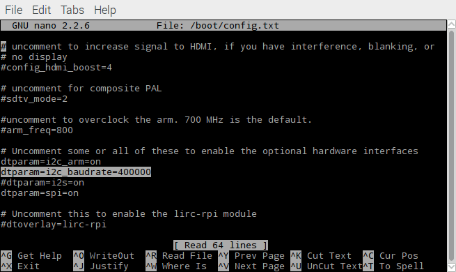
You need to reboot the pi for the setting to take effect.
The ISR processing time for three different values of the I2C baudrates is shown in the table below.
| Baud Rate (bits/sec) | Processing Time (milliseconds) |
| 32000 | 19.5 |
| 100000 (default) | 6.5 |
| 400000 | 1.7 |
An interrupt service routine processing time of 1.7ms enables us to achieve an interrupt frequency of around 500Hz, which is adequate for most high speed sampling applications. It is interesting to note that the processing times are much slower than what a simple data rate calculation given the baudrate would suggest. For example, at a baudrate of 100K, reading 14 bytes should take 14*8*1000/100000 = 1.12ms. However the actual processing time is almost 6 times higher. I’m not sure why this is so. If anyone knows, please let me know!
Interrupt Timing Issues
For efficient implementation and optimal performance of sensor fusion algorithms, it is important to be able to achieve constant rate sampling i.e., achieve a constant time interval between two samples. Since we are using IMU interrupts as our sampling mechanism, the constant rate sampling requirement means being able to receive interrupts at a constant rate. Receiving events at a constant rate can be problematic on non realtime operating systems such as Raspbian where multiple processes are running concurrently and the scheduler can schedule out the process hosting the interrupt service routine at will. To investigate these timing issues, we logged the time interval between two interrupts for different interrupt frequencies. The results are shown below. The interrupt frequencies can be set by setting the appropriate sample rate divider using the setRate function in the MPU6050 driver. For example, a 100 Hz sampling frequency can be achieved by calling setRate(9).
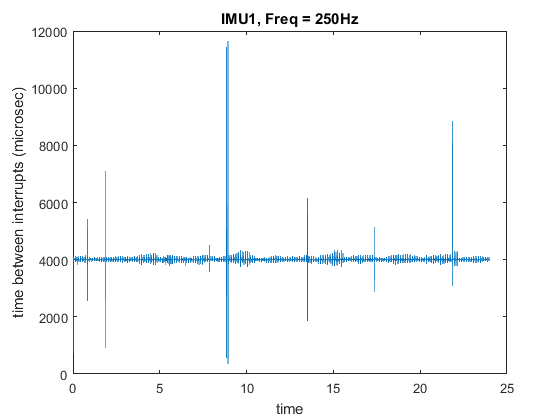
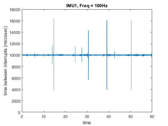
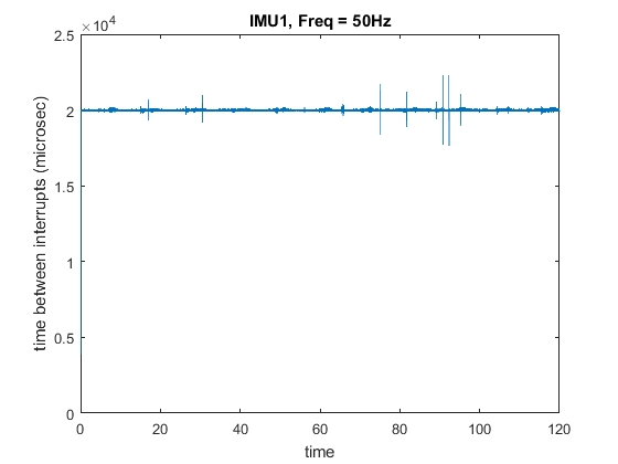
As can be seen, the sampling rate generally stays constant with small fluctuations, but suffers from occasional large deviations.
To verify that the fluctuations are due to the non-real time nature of the Rasbian operating system and not due to some other hardware/software issue, I connected a MPU6050 IMU to an Arduino Mega and configured it to send interrupts at 250Hz. The graph of the time interval between interrupts and the mean and variance of the time interval data is shown below.
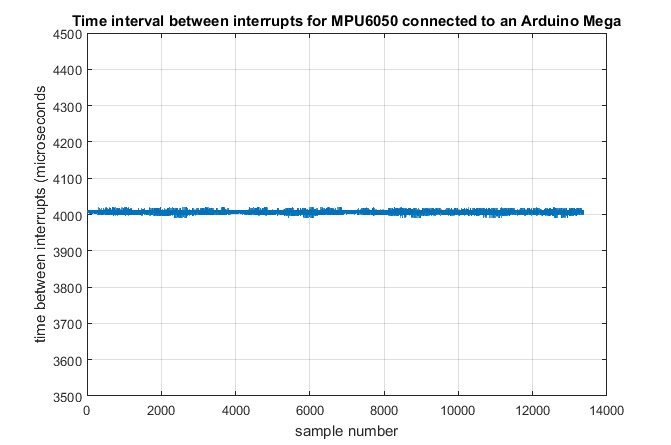
| Mean | Variance |
| 4006.9 | 18.73 (0.47%) |
So what can be done to achieve constant rate interrupts on the Pi?
Note that even at a sampling rate of 50Hz, there are large spikes in the inter-interrupt time. Thus, even if one performs high speed sampling plus simple data pre-processing such as low pass filtering on a dedicated microcontroller such as a Teensy or Arduino and send the averaged data to the Pi at a lower rate (say 50Hz), the problem of receiving this data at a constant rate remains. People have proposed applying the RT_PREEMPT patch and recompiling the Raspbian kernel to help achieve more deterministic timing. I have not tried this yet.
Visual GDB: A Great Visual Studio Plugin for working on the Pi
There is a never-ending debate about what is the most efficient way to develop on the Pi. An easy to use IDE with good editing and debugging support can have a dramatic impact on your productivity and help reduce frustration. When I started working on the Pi, I was developing directly on the Pi using codeblocks. While codeblocks is a usable IDE, it pales in comparison to the stability and features offered by Visual Studio. Furthermore, as fast as the Raspberry Pi 3 is with a 1.2GHz processor and 1GB Ram, working directly on the Pi can be frustrating as programs often freeze and occasionally crash, particularly if one is running multiple processor/memory heavy programs such as an internet browser. Wouldn’t it be nice if you could use Visual Studio running on your PC to develop, build and debug programs for the Pi?
It turns out that there is a great Visual Studio plugin called Visual GDB developed by a German company named Sysprogs (https://sysprogs.com/about/). Visual GDB allows you to develop your applications using the familiar and convenient environment of visual studio and build your application using either a locally installed ARM toolchain or directly on the Pi. The best feature of Visual GDB is a fantastic debugger integration, enabling you to set breakpoints and watch the value of program variables using the standard visual studio debugger. Indeed, one can often forget the program is actually executing on another computer! Visual GDB also offers a great integration with the visual studio output window, letting you see the output of your printf statements conveniently in the visual studio output window.
Visual GDB has a great set of tutorials on the website; if you would like to learn more, you should check out their tutorials and download a trial version. In the remainder of this post, I’ll touch upon a few issues that took me some time to figure out.
Visual GDB keeps the source files on your PC synced with the files on the Pi. If your source files are located in C:\MyProject\ on your PC, Visual GDB will copy these files to /tmp/VisualGDB/C/MyProject on the Pi. Any project dependencies such as include paths, shared lib names/paths can be specified in the appropriate cmake directives. For example, my project relies upon the WiringPi library. I installed the source for the WiringPi lib and built the binaries at /home/pi/3rdParty/wiringPi. I can specify the path for the header/lib files for the wiringPi library in my CMakeLists.txt as follows:
include_directories(/home/pi/3rdParty/wiringPi/devLib)
target_link_libraries(test_wiringPi -L”/home/pi/3rdParty/wiringPi/devLib” -lwiringPi)
If you are using the remote toolchain to build your program, you don’t need these dependencies installed on your PC.
Debugging your Program
When your are debugging your program, GDB will need to know the paths for any shared libraries (the Linux analogue of dlls) used by your program. These paths are set using the LD_LIBRARY_PATH variable. You can set this variable in Visual GDB Project Properties->Debug Settings. However, setting the LD_LIBRARY_PATH this way only works if you execute your program in the Visual GDB environment (for example by hitting F5 or Ctrl+F5) in Visual Studio. If you try to run the generated executable directly (coped by default to /tmp), you’ll get “can’t find .so file” error. You can set the path for your shared libraries by editing the /home/pi/.bashrc and add a export LD_LIBRARY_PATH line at the end. For example:
export LD_LIBRARY_PATH=/home/pi/3rdParty/wiringPi/devLib:LD_LIBRARY_PATH
Doing so makes the LIB_LIBRARY_PATH setting available for both GDB and standalone execution of your program. So you don’t need to set it separately in the Visual GDB Project Properties anymore.
Hi, very good article. Are you making your code available? I came across this article searching how best / easiest way to access the magnetometer.
Would you be willing to share your code, I’d be greatly appreciative? Tall ask indeed I know.
Sure, when I have some time, I’ll zip it up and post it. I’m not actively working on IMUs anymore, mostly working on deep learning now.
Hello, I was wondering if you still have the code available for this project?
I don’t anymore.. Not working on that stuff anymore